Zero Crossing Detector For Fm Demodulation - The block diagram and the output signal description of each block will be useful to the.
Zero Crossing Detector For Fm Demodulation - The block diagram and the output signal description of each block will be useful to the.. The output of your lpf will now vary from.4 v to.6v at 100hz rate. The various methods of fm demodulator are introduced. A zero crossing detector does not require full wave rectification. To provide an output signal whose amplitude is linearly. Now imagine that your fm signal is modulated by a 100hz signal such that its frequency varies from 800khz to 1.2mhz.
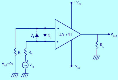
Zero crossing detector zero crossing detector is basic comparator circuit with zero reference voltage it is used to detect sinewave. I have already created an fm modulated signal,digitized it using a 12 bit adc.then i gave it to a limiter,differentiator.now i have a train of pulses which indicate positive zero crossings.how i can recover original message signal?.i tried using a monoshot as per theory.but it is actually not working. Zero crosssing detector is a form of comparator that can detect zero crossing of ac input signal. In receiver, the concept of demodulation plays a vital role. The mathematical description of zero crossing detector is explained.
A General Zero Crossing Demodulator Structure Download Scientific Diagram from www.researchgate.net A i am currently looking for a way to make a zero crossing detector (i.e. This circuit takes in frequency modulated rf signals and takes the modulation from the signal to output only the modulation that had been applied at the. 1) a lpf can be characterized in the frequency or time domain. The mathematical description of zero crossing detector is explained. We can make it using an opamp, as shown below, however using a opamp for. A zero crossing detector does not require full wave rectification. The block diagram and the output signal description of each. In inverting type zcd, zero crossing detection circuit, we connect zero voltage reference with a noninverting input pin as shown in this diagram.
Park an fm detector for low s/n, ieee trans on.
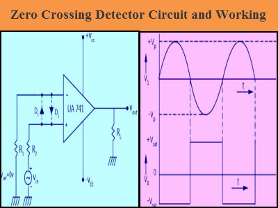
In this article, we discuss zero crossing detector in detail with two different circuits. Zero crosssing detector is a form of comparator that can detect zero crossing of ac input signal. Now imagine that your fm signal is modulated by a 100hz signal such that its frequency varies from 800khz to 1.2mhz. The various methods of fm demodulator are introduced. I need a zero crossing detector for a project i'm working on, and came across this design mentioned here on eevblog. In simple words, the comparator is a basic operational amplifier used to compare two voltages simultaneously and changes the o/p according to the comparison. This circuit takes in frequency modulated rf signals and takes the modulation from the signal to output only the modulation that had been applied at the. You only need the first half, hence only the one diode. To provide an output signal whose amplitude is linearly. Zero crossing detector circuit basically involves the sine to square wave conversion by a level detector circuit followed by a pulse circuit, which consists of one shot monostable circuit or a differentiator. Ratio detector with phase discrimination for fm demodulation in analog communication подробнее. In this video, i have explained fm demodulation by zero crossing detector by following outlines: The traditional zero crossing demodulator consists of three main parts, which are.
This circuit takes in frequency modulated rf signals and takes the modulation from the signal to output only the modulation that had been applied at the. The block diagram and the output signal description of each. A i am currently looking for a way to make a zero crossing detector (i.e. In this video, i have explained fm demodulation by zero crossing detector by following outlines: Zero crossing detector circuit basically involves the sine to square wave conversion by a level detector circuit followed by a pulse circuit, which consists of one shot monostable circuit or a differentiator.
Zero Crossing Detector Circuit And Its Applications from www.elprocus.com The block diagram and the output signal description of each block will be useful to the. Fm detection using zero crossing detector подробнее. In this video, i have explained fm demodulation by zero crossing detector by following outlines: In the initial paragraphs of the tutorial, you will learn zero crossing detector. The block diagram and the output signal description of each. Zero crossing detector circuit basically involves the sine to square wave conversion by a level detector circuit followed by a pulse circuit, which consists of one shot monostable circuit or a differentiator. The ideal zero crossing detector has infinite gain, and will change its output state at the exact moment the input signal passes through zero. A zero crossing detector does not require full wave rectification.
A zero crossing detector does not require full wave rectification.
The various methods of fm demodulator are introduced. The block diagram and the output signal description of each. I need a zero crossing detector for a project i'm working on, and came across this design mentioned here on eevblog. Demodulation using a zero crossing counter demodulator is demonstrated. In this video, i have explained fm demodulation by zero crossing detector by following outlines: Fm detection using zero crossing detector подробнее. The traditional zero crossing demodulator consists of three main parts, which are shown in figure 2.1. The first part is a zero crossing detector, which outputs a pulse at every zero crossing of the incoming signal. Hello, i am currently looking for a way to make a zero crossing detector (i.e. In the initial paragraphs of the tutorial, you will learn zero crossing detector. The traditional zero crossing demodulator consists of three main parts, which are. The first part is a zero crossing detector, which outputs a pulse at every zero crossing of the incoming signal. Zero crossing detector zero crossing detector is basic comparator circuit with zero reference voltage it is used to detect sinewave.
Fm detection using zero crossing detector подробнее. In this video, i have explained fm demodulation by zero crossing detector by following outlines: The traditional zero crossing demodulator consists of three main parts, which are shown in figure 2.1. In simple words, the comparator is a basic operational amplifier used to compare two voltages simultaneously and changes the o/p according to the comparison. Now imagine that your fm signal is modulated by a 100hz signal such that its frequency varies from 800khz to 1.2mhz.
Zero Crossing Detector Circuit And Its Applications from www.elprocus.com We can make it using an opamp, as shown below, however using a opamp for. Ratio detector with phase discrimination for fm demodulation in analog communication подробнее. The various methods of fm demodulator are introduced. The traditional zero crossing demodulator consists of three main parts, which are shown in figure 2.1. Hello, i am currently looking for a way to make a zero crossing detector (i.e. In receiver, the concept of demodulation plays a vital role. The first part is a zero crossing detector, which outputs a pulse at every zero crossing of the incoming signal. Park an fm detector for low s/n, ieee trans on.
A zero crossing detector circuit is mainly used for protecting electronic devices from switch on surges by ensuring that during power switch on the mains phase always enters' designing a zero crossing detector is not difficult.
In simple words, the comparator is a basic operational amplifier used to compare two voltages simultaneously and changes the o/p according to the comparison. Fm detection using zero crossing detector подробнее. I need a zero crossing detector for a project i'm working on, and came across this design mentioned here on eevblog. The mathematical description of zero crossing detector is explained. 1) a lpf can be characterized in the frequency or time domain. Hello, i am currently looking for a way to make a zero crossing detector (i.e. Ratio detector with phase discrimination for fm demodulation in analog communication подробнее. A zero crossing detector does not require full wave rectification. Demodulation using a zero crossing counter demodulator is demonstrated. Zero crossing detector circuit is similar to a comparator but one of the input pins connects with a ground terminal. The first part is a zero crossing detector, which outputs a pulse at every zero crossing of the incoming signal. The ideal zero crossing detector has infinite gain, and will change its output state at the exact moment the input signal passes through zero. Zero crosssing detector is a form of comparator that can detect zero crossing of ac input signal.
Related : Zero Crossing Detector For Fm Demodulation - The block diagram and the output signal description of each block will be useful to the..